LCA-13008-Replacement_Of_HE_Sensors_Procedure [lca-13008-replacement_of_he_sensors_procedure]#
Scope:
This document describes how to replace the Hall Effet Sensors listed below. Please read “initial configuration” and “staff required” sections that apply for each case.
1.1. Sensor_XP-LCA-13184-qty1 per AutoChanger 2
1.2. Sensor_XM-LCA-13166-qty1 per AutoChanger 3
1.3. Sensor_YM-LCA-13160-qty2 per AutoChanger 4
2.1. Truck_Sensor_Board_XM-LCA-13006-qty1 per AutoChanger 4
2.2. Truck_Sensor_Board_XP-LCA-13005-qty1 per AutoChanger 5
3.1. Truck_Position_Sensors_XM-LCA-12860-qty3 per AutoChanger 5
3.2. Truck_Position_Sensors_XP-LCA-12852-qty3 per AutoChanger 6
4.1. Limit_switch_position_sensor XP-LCA-13100-qty2 per AutoChanger 7
4.2. Limit_switch_position_sensor XM-LCA-13102-qty2 per AutoChanger 7
Initial configuration (for each case):
The autochanger is supposed to be empty (with no filter) on its Maintenance Bench #02-LCA-13140 in horizontal position (as shown on LCA-13140) in StandAlone configuration. It is connected to the electrical bay #04-LCA-13140. The three power supplies are turned off.
Staff required (for each case):
1 person with mechanical skills
1 person with electrical skills
1 person able to use the FCS
ONLINECLAMP SENSORS#
Sensor_XP-LCA-13184-qty1 per AutoChanger#
Scope:
This operation has to be considered if the position of the OnlineClamp X+ cannot be read on the FCS. Since every signal (OnlineClampX+ Open/OnlineClampX+ Closed) is doubled by a complementary one, the FCS is able to detect a sensor error.
The position of the Sensor_XP-LCA-13184 is given on #05-LCA-12946.
Material needed:
-
Small cross-point screwdriver qty 1
-
Small flat screwdriver qty 1
Procedure:
-
Make sure there is no filter in the AutoChanger and the power supplies are turned off.
-
Remove the connector by levering between the socket and the connector with a flat screwdriver. Make sure not to pull on the cable. The correct position at which the flat screwdriver has to be inserted is shown in below:
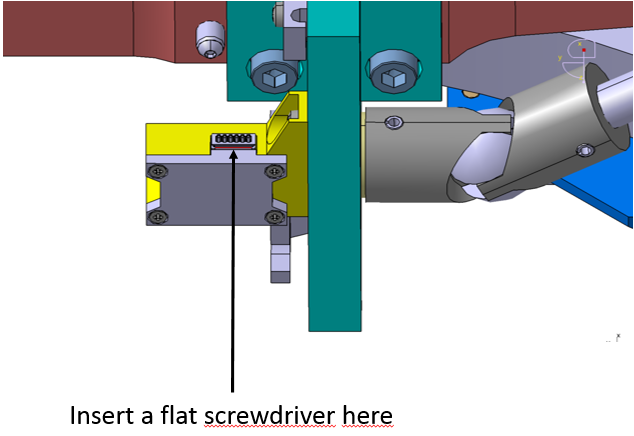
-
Remove the screw #06-LCA-13184 with a small cross-point screwdriver.
-
Pull the Sensor_XP and replace it by a new one. Make sure to fully insert the spigot of the Sensor_XP inside the clamp_XP #02-LCA-12946 as shown below:
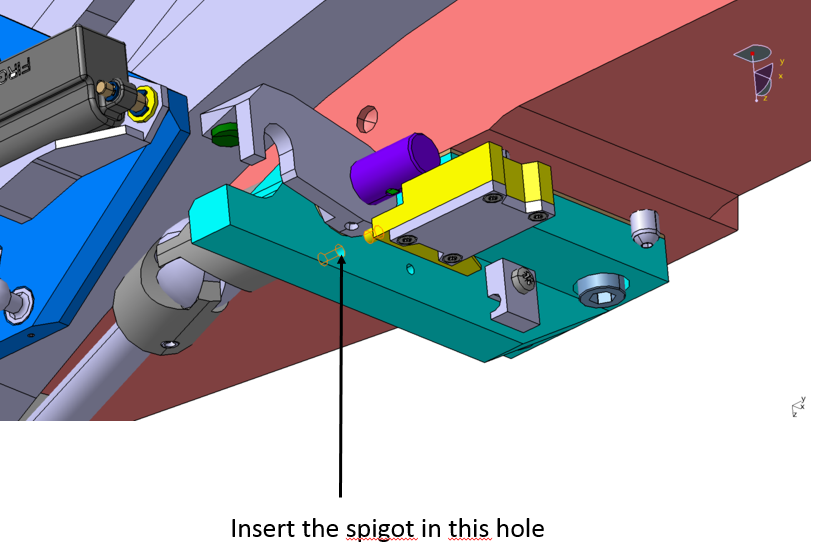
-
Screw in the screw #06-LCA-13184 with a small cross-point screwdriver.
-
Plug the connector to the socket by pushing on the connector without bending the cables.
Sensor_XM-LCA-13166-qty1 per AutoChanger#
Scope:
This operation has to be considered if the position of the OnlineClamp X-cannot be read on the FCS. Since every signal (OnlineClampX-Open/OnlineClampX-Closed) is doubled by a complementary one, the FCS is able to detect a sensor error.
The position of the Sensor_XM-LCA-13166 is given by #05-LCA-12991.
Material needed:
-
Small cross-point screwdriver qty 1
-
Small flat screwdriver qty 1
Procedure:
-
Make sure there is no filter in the AutoChanger and the power supplies are turned off.
-
Remove the connector by levering between the socket and the connector with a flat screwdriver. Make sure not to pull on the cable. The correct position at which the flat screwdriver has to be inserted is shown in below:
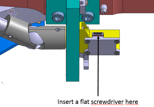
-
Remove the screw #06-LCA-13166 with a small cross-point screwdriver.
-
Pull the Sensor_XM and replace it by a new one. Make sure to fully insert the spigot of the Sensor_XM inside the clamp_XM #02-LCA-12991 as shown below:
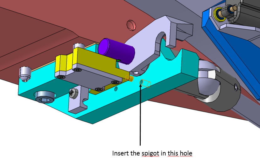
-
Screw in the screw #06-LCA-13166 with a small cross-point screwdriver.
-
Plug the connector to the socket by pushing on the connector without bending the cables.
Sensor_YM-LCA-13160-qty2 per AutoChanger#
Scope:
This operation has to be considered if the position of the OnlineClamp Y-cannot be read on the FCS. Since every signal (OnlineClampY-Open/OnlineClampY-Closed) is doubled by a complementary one, the FCS is able to detect a sensor error.
The position of the Sensors_XP-LCA-13184 is given by #06-LCA-13036.
WARNING: the sensor corresponding to the position OnlineClampY-Closed is on the left on LCA-13036 whereas the sensor corresponding to the position OnlineClampY-Open is on the right.
Material needed:
-
Small cross-point screwdriver qty 1
-
HE_Sensor_Unpluging_Tool LCA-12981 qty 1
Procedure:
-
Make sure there is no filter in the AutoChanger and the power supplies are turned off.
-
Unscrew the screw #06-LCA-13036 with a small cross-point screwdriver.
-
Unplug the connector of the sensor with the HE_Sensor_Unpluging_Tool LCA-12981. Make sure not to pull the cable but the connector.
-
Replace the Sensor_XP-LCA-13184 by a new one.
-
Screw in the the screw #06-LCA-13036 with a small cross-point screwdriver.
LATERAL LATCH DETECTION#
Truck_Sensor_Board_XM-LCA-13006-qty1 per AutoChanger#
Scope:
This operation has to be performed if the Lateral latch detection LCA-13005 or LCA-13006 does not work properly. For instance, Filter ID reading is incorrect. Other reasons are easy to detect since every signal is doubled by a complementary one (Latch Open/LatchClosed/Filter engaged). Thus, the FCS is able to detect a sensor error.
Material needed:
-
Small cross-point screwdriver qty 1
-
External (shaft) circlip plier qty 1
Procedure:
-
Make sure there is no filter in the AutoChanger.
-
Power on the AutoChanger by turning on the tree power supplies: Clean, Safety and Dirty powers on the electrical bay.
-
Move the trucks to position 680000 using “MoveToAbsoluteTargetPosition” command on the FCS. This position corresponds to the maximal elongation of the cables between the Swing arm Plates #01-LCA-12812/#03-LCA-12812 and the Truck Plates #01-LCA-12802/#02-LCA-1282.
-
Turn off Clean, Safety and Dirty powers supplies on the electrical bay.
-
Remove the 3 screws #15-LCA-12812 that are holding the cable clamps #04-LCA-12812 with a small cross-point screwdriver.
-
Unplug the connectors of the Latch Actuator #03-LCA-12829 and those of the Lateral latch detection LCA-13005/ LCA-13006. Make sure not to pull on the cable but only on the connectors.
-
Remove the circlips #12-LCA-12802 using an external circlip plier.
-
Thoroughly remove shim rings #10-LCA-12802 and #11-LCA-12802. Make sure to identify them since you will need to put them back at the same location (thickness varies on each side of swing arm plate X minus #03-LCA-12812). Please note there is no shim rings on X plus side.
-
Unscrew the screw #15-LCA-12812 that is holding the cap #19-LCA-12812 with a small screwdriver.
-
Remove cap #19--LCA-12812 (for X plus side) or #20--LCA-12812 (for X minus side).
-
Replace the Lateral latch detection #18-LCA-12812 (for X minus side) or #17-LCA-12812 (for X plus side) by a new one.
-
Make sure there is no electrical contact between Swing arm plates #01-LCA-12812/#03-LCA-12812 and the Lateral latch detection #18-LCA-12812/17-LCA-12812. This is granted by the insulators #16-LCA-12812.
-
Put the cap #19-LCA-12812 (for X plus side) or #20-LCA-12812 (for X minus side) back.
-
Screw them by tightening #15-LCA-12812 with a small cross-point screwdriver.
-
Put back shim rings #10-LCA-12802, swing arm plate X minus #03-LCA-12812, shim rings #11-LCA-12802. (only swing arm plate X plus #01-LCA-12812 for X plus side).
-
Mount the circlips #12-LCA-12802 using a circlip plier.
-
Plug the connectors of the Latch Actuator #03-LCA-12829 and those of the Lateral latch detection LCA-13005/ LCA-13006.
-
Put the cables inside the cable clamps #04-LCA-12812 and tighten the screws #15-LCA-12812 with a small cross-point screwdriver. Make sure not to pinch the cables.
-
Power back on the autochanger by turning on Clean, Safety and Dirty power supplies on the electrical bay #04-LCA-13140.
-
Move the trucks to HandOff position using the command “GoToHandOff”.
Truck_Sensor_Board_XP-LCA-13005-qty1 per AutoChanger#
Please see section 2.1.
TRUCK POSITION SENSORS#
Truck_Position_Sensors_XM-LCA-12860-qty3 per AutoChanger#
Scope:
Replacement of Truck_Position_Sensors_XM-LCA-12860 has to be considered if the position of the truck X-cannot be read on the FCS for any of these three positions:
-
Online position (X-)
-
HandOff position (X-)
-
StandBy position (X-)
Since each of these 3 signals is doubled by a complementary one, the FCS is able to detect a sensor error.
The positions of Truck_Position_Sensors_XM-LCA-12860 are given by #03-LCA-13217. From top to bottom: HandHoff position – Online position – StandBy position.
Material needed:
-
HE_Sensor_Unpluging_Tool LCA-12981 qty 1
-
Small cross-point screwdriver qty 1
Procedure:
-
Make sure there is no filter in the AutoChanger and the power supplies are turned off.
-
Unplug the connector of the sensor with the HE_Sensor_Unpluging_Tool LCA-12981. Make sure not to pull the cable but the connector.
-
Unscrew the screw #05-LCA-12860 with a small cross-point screwdriver.
-
Replace the sensor Truck_Position_Sensors_XM-LCA-12860 by a new one.
-
Screw in the screw #05-LCA-12860 with a small cross-point screwdriver.
-
Plug back the connector on its socket. Make sure not to force on the cables but on the connector.
Truck_Position_Sensors_XP-LCA-12852-qty3 per AutoChanger#
Scope:
Replacement of Truck_Position_Sensors_XP-LCA-12852 has to be considered if the position of the truck X-cannot be read on the FCS for any of these three positions:
-
Online position (X+)
-
HandOff position (X+)
-
StandBy position (X+)
Since each of these 3 signals is doubled by a complementary one, the FCS is able to detect a sensor error.
The positions of the Truck_Position_Sensors_XP-LCA-12852 is given by #04-LCA-13217. From top to bottom: HandHoff position – Online position – StandBy position.
Material needed:
-
HE_Sensor_Unpluging_Tool LCA-12981 qty 1
-
Small cross-point screwdriver qty 1
Procedure:
-
Make sure there is no filter in the AutoChanger and the power supplies are turned off.
-
Unplug the connector of the sensor with the HE_Sensor_Unpluging_Tool LCA-12981. Make sure not to pull the cable but the connector.
-
Unscrew the screw #05-LCA-12852 with a small cross-point screwdriver.
-
Replace the sensor Truck_Position_Sensors_XP-LCA-12852 by a new one.
-
Screw in the screw #05-LCA-12852 with a small cross-point screwdriver.
-
Plug back the connector on its socket. Make sure not to force on the cables but on the connector.
LIMIT SWITCHES#
Limit_switch_position_sensor XP-LCA-13100-qty2 per AutoChanger#
This limit switch is currently not used. However, it can be replaced by the following manner:
-
Remove the screw #07-LCA-13100 with a 2mm hex. key
-
Unplug the connector with the tool: HE_Sensor_Unpluging_Tool LCA-12981
-
Replace the sensor by a new one.
-
Screw in the screw #07-LCA-13100 with a 2mm hex. key.
-
Plug back the connector to its socket by pushing on the connector. Make sur not to force on the cables.
Limit_switch_position_sensor XM-LCA-13102-qty2 per AutoChanger#
This limit switch is currently not used. However, it can be replaced by the following manner:
-
Remove the screw #07-LCA-13102 with a 2mm hex. key
-
Unplug the connector with the tool: HE_Sensor_Unpluging_Tool LCA-12981
-
Replace the sensor by a new one.
-
Screw in the screw #07-LCA-13102 with a 2mm hex. key.
-
Plug back the connector to its socket by pushing on the connector. Make sur not to force on the cables.