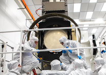
Ring gear lubrication
| title | Ring Gear Lubrication ( Carousel ) | LCA-xxxxxx | |
|---|---|---|---|
 | Traveler for intervention on The Filter Exchange System & Filter Exchange system parts | Approval Status | DRAFT |
| Rev. | Revision Description | LCN# | Date |
| A | Initial release, D.Laporte | 09-Apr-20 | |
| A.2 | Updated to word + new comments, P.Antilogus | 22-Apr-20 |
| Camera Doc ID | Atrium Doc ID | Validated By | Validation Date |
|---|---|---|---|
| LCA-xxxxx | xxxxxxx |
| Initials: | Date: | ||
|---|---|---|---|
| Traveler initiated: | |||
| Traveler Closed Out: |
| Part Serial Number: | Do not apply to this case |
| Index Key | Value |
|---|---|
| Subsystem | Carousel |
| Operation Type | On Camera Maintenance |
| System&Action | Driving Lubrication |
| Operation Name | Ring Gear Lubrication |
| Operation Time | \~1-2h |
| Operation Description | Lubrication of the main carousel gear. The lubricant is applied through a dedicated tool replacing temporarily one of the carousel break. |
| Triggered by Maintenance | Regular lubrication of the main carousel gear is expected. The frequency of lubrication has still to be determined. It is expected that it will be at a lower frequency than the scheduled maintenance period of the camera ( \~ 2 years) . |
| Triggered by Monitoring Analysis | Analyzing the power consumption during filter exchange and the fft of full carousel rotations, should allow to identify an increase in friction, the identification of the issue / which rotating part is involved in the performance degradation, is still under investigation. |
| Triggered by Incident recovery | Unlikely |
| Traveler Steps | |||
|---|---|---|---|
| 10 | WARNINGS (Personnel Safety Hazards / PPE) | ||
| 20 | CAUTIONS (Equipment Damage Hazards) | ||
| 20,10 | Do no pull on cables to prevent even small tension loads from overloading single wires and breaking them | ||
| 20,20 | Be careful to not drop/spread grease, ex: Brake teethes will have grease | ||
| 30 | Applicable Documents and Drawings | Ref./link | Type |
| 30,10 | Mobile Carousel Assembly | LCA-12500 | Drawing |
| 30,20 | Assembly Gear | OSNLT229 | Drawing |
| 30,30 | Brake Assembly | OSNLT712 | Drawing |
| 30,40 | Crown grease injector | LCA-128xx OSNLT794 | |
| 30,50 | Brake Assembly Uninstall Procedure | LCA-XXXXX | Document |
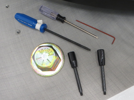
| 40 | Tools Required | Ref. | Quantity |
| 40,10 | Hexagonal key n04 | 1 | |
| 40,20 | Hexagonal key n06 | 1 | |
| Remarque : dans la photo il y a une 3 ieme clef ? | |||
| 50 | Parts, Materials, and Consumables | Ref. | Quantity |
| 50,10 |
Carousel breaks & motor handles | LCA-xxxx | 2 |
| 50,20 | Ring gear grease (Kluber ? ) | xxxxx | X ml |
| 60 | Useful Comments & Remarks | ||
| 60,10 | When unpowered the brakes are locked, preventing carousel rotation. Removing a single break from the carousel, leaving the two other in place , will still grant that the carousel , even unbalanced, will not move. | ||
| 60,20 | TBD A procedure to remove old grease has still to be defined. | ||
| 100 | Screw handles on brake support | Initials | Date |
|---|---|---|---|
| 100,10 | There is 3 breaks on the carousel ( Bay X,Y,Z) . For the lubrication of the ring gear we recommend to remove the break from Bay X TBD : We should identify which bay is the best for this operation | ||
| 100,20 | The bay protection panel should be removed | ||
| 100,10 | 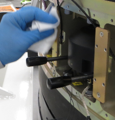 | ||
| The 2 breaks & motor handles should be put in place on the brake frame, to have an easy way to handle a brake once it will be unscrewed from the back flange. | |||
| 200 | disconnect brake sensor | Initials | Date |
| 200,10 | 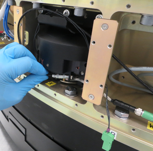 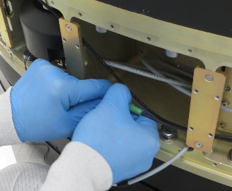 | ||
| To disconnect the brake sensor will request to access/open the neighbor bay | |||
| 300 | remove backflange parts x2 , with 2 screws each | Initials | Date |
| 300,10 | 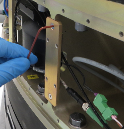 | ||
| 400 | Unscrew M6X30 (x4) | Initials | Date |
|---|---|---|---|
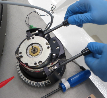
| 400,10 | 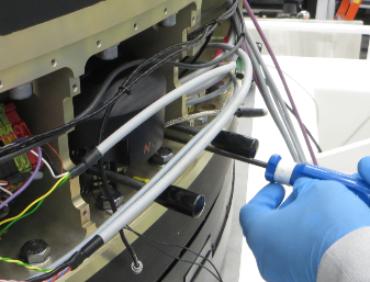 | ||
| 500 | lift the brake with the handles | Initials | Date |
| 500,10 |
As you lift out the break with the handles, be carefull to not spread grease all over the place (grease is on the gear side) , and avoid the backflange wires on the way out . | ||
| 600 | The socket is empty, check the access to the ring gear | Initials | Date |
|---|---|---|---|
| 600,10 | 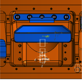 | ||
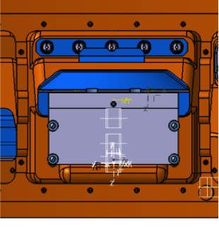
| 700 | Present the grease injector | Initials | Date |
| 700,10 | 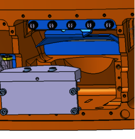 | ||
| 800 | Screw the grease injector | Initials | Date |
screw M6X30 (x4) , the screws are from the step 400,10 | |||
| 900 | Grease pump connection | Initials | Date |
|---|---|---|---|
| 900,10 | TBD picture | ||
| 1000 | Gear rotation | Initials | Date |
| 1000,10 | TBD Mode ? Speed ? Programme fcs ? Time? | ||
| 1100 | Remove grease injector | Initials | Date |
| 1100,10 | TBD | ||
| 1200 | Cleaning | Initials | Date |
| 1200,10 | TBD | ||
| 1300 | lift the brake with the handles | Initials | Date |
| 1300,10 |
As you lift in the break with the handles, be carefull to not spread grease all over the place (grease is on the gear side) , and avoid the backflange wires on the way in . TBD : to realy fit in the break should be free , but it is locked as unpowered , what do we do ? | ||
| 1400 | Screw back the brake : M6X30 (x4) | Initials | Date |
|---|---|---|---|
| 1400,10 | | ||
| 1500 | Reconnect brake sensor | Initials | Date |
| 1500,10 | | ||
| Remark: on the pictures the 2 back flange parts are already put back in place , but we recommend to mount them after this step . ( NEW PICTURES ? ) | |||
| 1600 | Remount backflange parts x2 , with 2 screws each | Initials | Date |
| 1600,10 | | ||
| 9999 | End Of Traveler | Initials | Date |
|---|---|---|---|
| 9999,10 | Work complete | ||